0 Items

POINT OF CARE UTRASOUND (11)

Friday, 24 October 2025 19:20

OBS SONOGRAPHY

Written by


1. What is Obstetric Ultrasound?

  • Obstetric ultrasound (also called prenatal ultrasound or obstetric sonography) uses high-frequency sound waves (via a transducer) to obtain images of the pregnant uterus, the embryo/fetus, placenta, amniotic fluid and maternal pelvic anatomy. 

  • It does not use ionising radiation and is considered very safe when used appropriately. 

  • It is widely used in obstetrics for dating the pregnancy, assessing viability, anatomy, growth, and monitoring for complications.


2. Techniques & Modalities

https://www.parents.com/thmb/JftSIhG6FnT4379mh9e6QNgoBBQ%3D/1500x0/filters%3Ano_upscale%28%29%3Amax_bytes%28150000%29%3Astrip_icc%28%29/twin-ultrasound-106005791-5b8d9f79c9e77c002ca1159b.jpg


Approaches

  • Transabdominal ultrasound: The usual approach for many gestational ages — a curvilinear (or sector) probe is placed on the mother’s abdomen with ultrasound gel. Useful once uterus is large enough. 

  • Transvaginal ultrasound: Especially useful in early pregnancy (e.g., 10 weeks) or when higher resolution of the cervix or lower uterine segment is needed. 

Advanced/Additional Modes

  • 2D (B-mode): Standard grayscale imaging.

  • Doppler ultrasound: To assess blood flow (e.g., umbilical artery, middle cerebral artery, fetal heart) — helpful in growth restriction or high-risk pregnancies. 

  • 3D and 4D ultrasound: (Three-dimensional imaging, real-time four-dimensional) used increasingly for fetal anatomy or research/parental imaging but not always part of routine scanning protocols. 


3. Common Indications & What We Look For

https://my.clevelandclinic.org/-/scassets/images/org/health/articles/22644-20-week-ultrasound
6

Key Uses

  • Confirm the presence of a live intrauterine pregnancy (embryo/fetal heart motion) and exclude ectopic pregnancy. 

  • Estimate gestational age (dating) and set an estimated due date (EDD). 

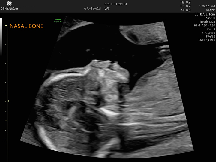
  • Assess fetal anatomy (especially in the second trimester, e.g., ~18-22 weeks) to identify structural anomalies. 

  • Monitor fetal growth, amniotic fluid volume, placental location and maturity, fetal presentation (cephalic, breech), multiple pregnancies. 

  • Evaluate maternal pelvic structures (uterus, cervix, ovaries) when relevant (e.g., shortened cervix, placenta previa).

Timing of Routine Scans

  • Many guidelines recommend at least two scans in an uncomplicated pregnancy: one in the first trimester (or early second) for dating and viability, and an anatomy scan in the mid-second trimester (≈18-20 weeks). 

  • More frequent or specialized scans may be used in high-risk pregnancies.


4. Key Measurements and Fetal Biometry

https://i.ytimg.com/vi/jcUOysiaLM8/maxresdefault.jpg?rs=AOn4CLClycVt5uelCd4Wsk21fk6nJnIofQ&sqp=-oaymwEmCIAKENAF8quKqQMa8AEB-AH-CYAC0AWKAgwIABABGGsgayhrMA8%3D
 

Some of the important biometry measurements include:

  • Biparietal diameter (BPD) — measurement across fetal head. 

  • Head circumference (HC)

  • Abdominal circumference (AC)

  • Femur length (FL)
    These are used to estimate fetal weight, growth trajectory, gestational age.


5. Limitations & Pitfalls

  • Accuracy depends on operator skill, fetal position, maternal habitus (e.g., obesity), gestational age.

  • Some anomalies may not be detectable with ultrasound (depends on severity, timing, resolution).

  • Although considered safe, non-medical use (e.g., “keepsake” videos) is discouraged by authorities. 


6. Safety Considerations

  • Diagnostic obstetric ultrasound has been extensively studied and no known harmful effects have been conclusively demonstrated when used properly. 

  • The principle of ALARA (“as low as reasonably achievable”) applies — minimal exposure for diagnostic need.

  • Doppler mode involves higher acoustic output, so its use should be justified.


7. Practical Tips for the Sonographer/Clinician

  • Ensure the patient is comfortable; for transabdominal scans a partially full bladder may help in early pregnancy for better image window.

  • Use appropriate probe (curvilinear for abdomen; endovaginal for transvaginal).

  • Optimize image settings: depth, gain, focus, probe orientation.

  • Always document standard views and measurements; include fetal heart rate, placental location, amniotic fluid index (AFI) or deepest vertical pocket.

  • Correlate with clinical context (LMP, prior scans, risk factors).

  • Communicate findings clearly and document any abnormalities or concerns for further referral.


8. Summary


Ultrasound in obstetrics is an indispensable, safe, non-invasive imaging modality that allows assessment of fetal viability, growth, anatomy, and maternal structures. As a medical student (which I understand you are), mastering the common indications, standard planes and measurements will greatly aid your clinical competence in obstetrics and fetal imaging.

Friday, 24 October 2025 18:53

THYROID SONOGRAPHY

Written by


Introduction

Thyroid ultrasound (or thyroid sonography) is a non-invasive imaging technique that uses high-frequency sound waves to visualise the thyroid gland (lobes and isthmus), adjacent structures (such as trachea, carotid artery, jugular vein), and any abnormalities (nodules, cysts, thyroiditis, goitre). 
It’s widely used in endocrinology and radiology for evaluation of thyroid size, texture, nodules, vascularity, and lymph-nodes in the neck. 


Indications

  • Evaluation of a palpable thyroid nodule or neck mass. 

  • Assessment of thyroid enlargement (goitre) or asymmetry of lobes. 

  • Follow-up of known thyroid nodules (monitor growth or change in characteristics). 

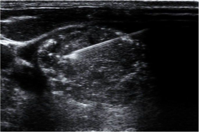
  • Guidance for fine-needle aspiration (FNA) of thyroid nodules or suspicious lymph nodes. 

  • Evaluation of suspected thyroiditis (e.g., Hashimoto’s thyroiditis or Graves’ disease) or abnormal cervical lymph nodes. 


Normal Sonographic Appearance

https://www.researchgate.net/publication/344269894/figure/fig2/AS%3A954245838827520%401604521345372/Thyroid-ultrasound-longitudinal-view-revealed-that-the-thyroid-gland-was-normal-in-size.png
6
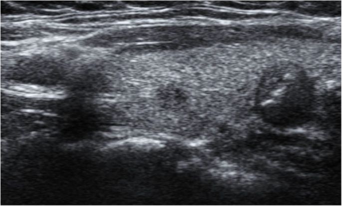
  • The thyroid gland typically has a homogeneous echotexture, meaning the internal echoes are uniform throughout the lobes and isthmus. 

  • Echogenicity: medium to slightly high relative to surrounding neck muscles (strap muscles). 

  • The lobes are connected by an isthmus; in transverse view it appears anterior to trachea. 

  • Normal vascularity: visible but not overly dominant; Doppler flow should show scattered vessels, not an “inferno” pattern. 

  • Measurements: Adult lobe typically length ~4–6 cm, AP 1.3–1.8 cm; isthmus thickness usually 1 cm. 


Key Technical Protocol / Views

https://www.researchgate.net/publication/236665253/figure/fig1/AS%3A213964966371328%401428024631294/Ultrasound-Thyroid-ultrasound-transverse-A-B-and-C-and-sagittal-view-D-and-E-of-the.png
6
  • Patient lies supine, neck slightly extended. Gel applied over lower neck. 

  • Transducer placed for transverse view at midline (isthmus) and then over lobes for transverse sweep (superior → middle → inferior). 

  • Longitudinal (sagittal) view of each lobe (right and left) is obtained to measure craniocaudal length and AP dimension. 

  • Colour or power Doppler is used to assess vascularity of gland/nodules. 

  • Measurements: record length × width × height (or AP) of each lobe and isthmus. Document any nodules (size, echogenicity, margins, calcifications). 


Sonographic Features of Abnormalities / Nodules

https://media.springernature.com/lw685/springer-static/image/art%3A10.1186%2Fs43055-021-00498-x/MediaObjects/43055_2021_498_Fig2_HTML.png
6

From the pictorial review by British Thyroid Association (U1–U5 classification) and other sources: 

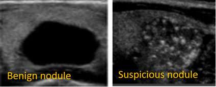
Benign features

  • Iso- or hyperechoic nodules with a halo (thin echogenic rim) often indicate benignity. 

  • Coarse “comet-tail” artifacts and macro-calcifications may favour benign colloid nodules. 

  • Spongiform appearance (microcystic change) is low suspicion.

Suspicious/malignant features

  • Hypoechoic nodules (especially markedly hypoechoic) compared to normal thyroid tissue. 

  • Irregular margins, taller-than-wide shape on transverse image. 

  • Micro-calcifications (tiny punctate echogenic foci) within a nodule: strongly suspicious for Papillary thyroid carcinoma. 

  • Increased central vascularity on Doppler, or “thyroid inferno” pattern (seen in Graves’ disease).

  • Solid component, absence of halo, extrathyroidal extension, abnormal lymph nodes.

Thyroiditis / Diffuse disease

  • Heterogeneous gland echotexture, reduced echogenicity, increased vascularity. 

  • In acute/subacute thyroiditis: may see hypoechoic areas, fluid collections.


How to Interpret & Report

When interpreting a thyroid ultrasound, consider:

  • Size, shape, and volume of each thyroid lobe & isthmus.

  • Echotexture and echogenicity of gland.

  • Presence of nodules: number, size, location (which lobe, upper/mid/lower), composition (solid, cystic, mixed), echogenicity, margin, calcifications, vascularity.

  • Adjacent structures: cysts, lymph nodes (cervical chain), extrathyroidal extension.

  • Colour-Doppler findings (vascularity).

  • Recommendation: Is follow-up required? FNA indicated? TI-RADS classification (or equivalent) may be used. 


Advantages & Limitations

Advantages

  • Painless, no ionising radiation, real-time imaging. 

  • High sensitivity for detection of nodules even when non-palpable. 

  • Guides fine-needle aspiration safely.

Limitations

  • Operator-dependent; image quality varies with skill and equipment.

  • Ultrasound alone cannot definitively diagnose malignancy — features suggest risk, but cytology/histology often needed. 

  • Some nodules deep, retrosternal or with calcified capsule may be difficult to visualise fully.

  • Acoustic shadowing (from calcifications), artefacts may obscure some regions. 


Practical Tips for Performing the Exam

  • Use a high-frequency linear transducer (7–15 MHz) for superficial structure resolution.

  • Ask patient to tilt head slightly backward (neck extended) to improve access.

  • Apply sufficient gel, avoid air between probe and skin.

  • Sweep systematically: midline isthmus, right lobe (superior to inferior), left lobe similarly; obtain transverse and longitudinal views. 

  • Measure nodules in three dimensions (length, width, depth) and record location (e.g., right lobe upper pole).

  • Use colour/power Doppler to assess vascularity especially if suspicion of thyroiditis or malignancy.

  • Compare with previous studies (if any) for size change.

  • Document any lymphadenopathy in the neck (especially lateral cervical).


Summary

Thyroid sonography is an essential imaging tool in evaluating thyroid pathology. Understanding the normal appearance, being familiar with the protocol views, recognising benign vs suspicious features, and appreciating its strengths and limitations will enable accurate reporting and better clinical decision-making.


A. Thyroid Cyst

  • Anechoic, well-circumscribed, posterior acoustic enhancement
    📸
    Cyst


B. Colloid Nodule

  • Isoechoic/hyperechoic

  • Comet-tail artifacts (bright echoes)
    📸
    Colloid Nodule


C. Thyroid Adenoma

  • Well-defined capsule, peripheral halo

  • Homogeneous, hypoechoic
    📸
    Adenoma


D. Papillary Carcinoma

  • Hypoechoic, irregular margins

  • Microcalcifications (tiny white dots)

  • Taller-than-wide shape
    📸
    Papillary Carcinoma


E. Multinodular Goitre

  • Multiple nodules

  • Heterogeneous echotexture
    📸
    Goitre


F. Hashimoto’s Thyroiditis

  • Diffusely hypoechoic, coarse echotexture

  • Increased vascularity
    📸
    Hashimoto


G. Graves’ Disease

  • “Thyroid inferno” on color Doppler (diffuse flow)
    📸
    Thyroid Inferno


5️⃣ TI-RADS Classification (Simplified)

TI-RADS Grade Risk Level Sonographic Findings Management
1 Normal Homogeneous gland None
2 Benign Spongiform or cystic No FNA
3 Mild Suspicion Isoechoic, smooth margin Monitor
4 Moderate Suspicion Hypoechoic, irregular margin FNA if >1 cm
5 Highly Suspicious Microcalcifications, taller-than-wide FNA >1 cm, surgical review

6️⃣ Reporting Template

Patient: Name / Age / Gender
Indication: Thyroid swelling, neck mass, follow-up, etc.
Technique: High-frequency linear probe (7–15 MHz), transverse and sagittal views.

Findings:

  • Right lobe: [Dimensions, echogenicity, nodules]

  • Left lobe: [Dimensions, echogenicity, nodules]

  • Isthmus: [Thickness, texture]

  • Vascularity: [Normal / Increased / Decreased]

  • Cervical lymph nodes: [Normal / Abnormal]

Impression:

  • Normal thyroid OR suggestive of [nodule type / thyroiditis / goitre].

  • TI-RADS score: [Insert grade].

  • Recommendation: FNA, repeat scan in 6–12 months, or referral to endocrinologist.


7️⃣ Case Studies (Educational)

Case 1: Benign Colloid Nodule

  • 45-year-old female with anterior neck swelling.

  • Ultrasound: Isoechoic lesion, comet-tail artifact, peripheral halo.

  • Impression: TI-RADS 2 (Benign).

  • FNA: Colloid nodule.


Case 2: Papillary Thyroid Carcinoma

  • 32-year-old female, right lobe hypoechoic nodule with microcalcifications, irregular margin.

  • TI-RADS 5

  • Histology: Papillary carcinoma confirmed.


Case 3: Hashimoto’s Thyroiditis

  • 40-year-old female with fatigue and neck discomfort.

  • Ultrasound: Diffuse hypoechogenicity, coarse texture, increased vascularity.

  • Thyroid antibodies: Positive anti-TPO.


8️⃣ Practical Checklist (for Students and Sonographers)

Step Task
Prepare high-frequency probe and patient in supine position
Check gel, wipe air bubbles
Start at isthmus (transverse), sweep both lobes
Rotate probe for sagittal (longitudinal) view
Measure each lobe (L×W×H)
Record echogenicity, nodules, and vascularity
Use Doppler for diffuse or focal flow
Evaluate cervical lymph nodes
Save images and measurements
Complete structured report

9️⃣ Summary Points

  • Thyroid ultrasound is the first-line imaging for all thyroid diseases.

  • Differentiates solid vs cystic and benign vs suspicious lesions.

  • Doppler helps assess vascularity in Graves’ or thyroiditis.

  • TI-RADS aids standardization and FNA decision-making.

  • Always correlate with clinical and biochemical findings (TSH, T3, T4, antibodies).


Thursday, 23 October 2025 17:27

CHEST SONOGRAPHY

Written by


Chapter: Chest Ultrasound (POCUS)

1. Introduction


2. Anatomical & Sonographic Basics

2.1 Key Anatomy

  • Chest wall (skin → subcutaneous tissue → ribs → intercostal spaces)

  • The pleural interface: the parietal pleura (lining chest wall) and visceral pleura (covering lung)

  • The lung parenchyma filled with air (which usually impedes ultrasound beyond the pleura)

  • Diaphragm, liver (right side) and spleen (left side) serve as acoustic windows for inferior lung and pleural spaces. 

2.2 Sonographic Landmarks

  • Pleural line: a bright, hyperechoic horizontal line just beneath the rib shadows, representing the interface of parietal & visceral pleura. 

  • Rib shadows: When scanning longitudinally in an intercostal space, the ribs appear as bright lines with acoustic shadow behind. Useful to confirm correct probe positioning. 

  • “Bat sign”: The two adjacent rib shadows appear like wings and the pleural line the body of the bat — useful to confirm correct intercostal window. 

2.3 Ultrasound Artifacts & Their Meaning

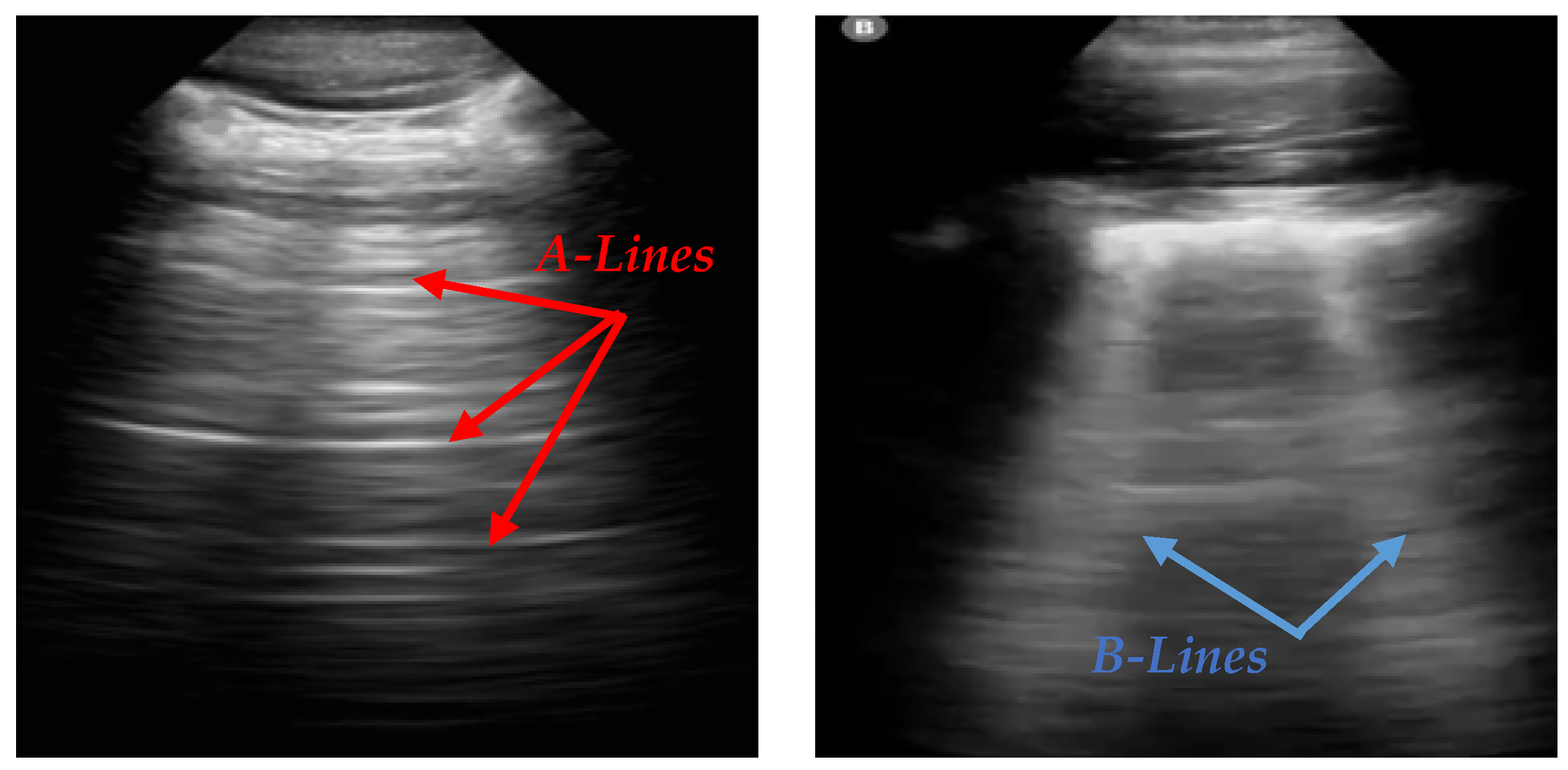
  • A-lines: Horizontal, equidistant echogenic lines parallel to the pleural line. These arise due to reverberation in an aerated lung. 

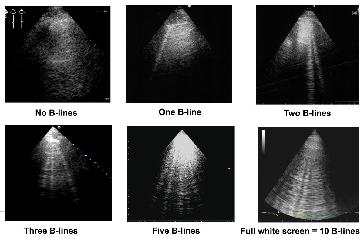
  • B-lines: Vertical, laser-like hyperechoic lines emanating from the pleural line, extending to the bottom of the screen, moving with lung sliding. They represent increased lung density/interstitial fluid. 

  • Lung sliding: The shimmering motion of the pleural line as the visceral pleura glides over the parietal pleura during respiration. Its presence argues against pneumothorax in the scanned zone. 

  • M-mode signs: In M-mode ultrasound, a normal sliding pleura produces the “seashore sign” (static tissue above pleura, granular below). In pneumothorax, absence of sliding gives a “barcode/stratosphere sign”. 


3. Equipment & Scanning Technique

3.1 Probe Selection

  • Linear probe (5-10 MHz): Ideal for superficial structures (pleural line, pneumothorax detection) due to high resolution.

  • Curvilinear / phased array (2-5 MHz): Better penetration for deeper lung fields, pleural effusions, deeper consolidations.

3.2 Machine Settings & Positioning

  • Use a depth of ~4-8 cm for pleural line scanning; increase depth up to ~15 cm for deeper lung/effusion assessment.

  • Focus at pleural line. Reduce gain if artifacts (lines) are too bright or obscured.

  • Patient positions:

    • Anterior chest: supine or semi-recumbent.

    • Lateral/posterior: sitting or lateral decubitus, especially for posterior lung zones or pleural effusion.

3.3 Scanning Zones and Windows

  • Standard windows: anterior upper/lower, lateral upper/lower (each side) — sometimes posterior zones added. 

  • The probe is placed perpendicular to the ribs in an intercostal space, with the marker toward the patient’s head (for longitudinal view) or toward the right side (for transverse).

  • Identify the rib shadows, pleural line, then assess artefacts (A-lines, B-lines), sliding, and deeper lung texture.


4. Normal Lung Ultrasound Appearance

6

Key features of a normal scan in an aerated lung:

  • Pleural line present, shimmering with respiration (lung sliding).

  • A-lines present (horizontal) beneath pleural line in many views, indicating air beneath. 

  • At most 0-2 B-lines in any given intercostal zone (especially dependent zones) — more B-lines suggest pathology. 

  • Curtain sign: At the lung base the moving lung “curtain” covers the diaphragm/liver or spleen with inspiration, arguing against large pleural effusion. 


5. Pathological Findings & Their Ultrasound Patterns

5.1 Pneumothorax

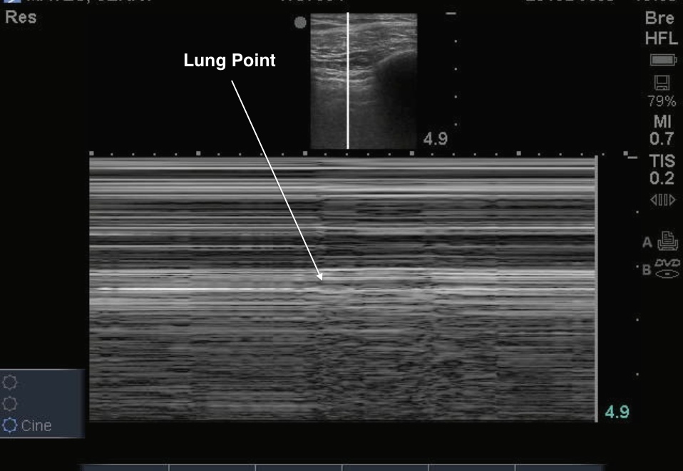
https://med.emory.edu/departments/emergency-medicine/_images/ultrasound/image-week/lung-point-still-labeled.jpeg
6

Ultrasound findings suggestive of pneumothorax:

  • Absence of lung sliding (pleural line static).

  • Absence of lung pulse (if ventilation suppressed but heart still generating pleural micro-movements).

  • Presence of A-lines only (air only) in the zone.

  • Lung point: Transition zone between sliding pleura and non-sliding pleura — highly specific for pneumothorax. 

  • M-mode: “Barcode/stratosphere sign” instead of “seashore sign”. 

5.2 Interstitial Syndrome / Pulmonary Edema

 
6

When there is increased lung density (fluid, fibrosis, interstitial thickening), typical signs include:

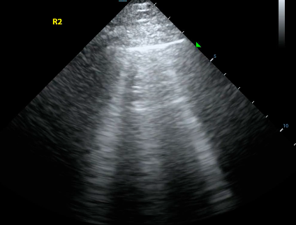
  • Multiple B-lines (≥ 3 in a zone) that move with respiration, extend to bottom of screen, erase A-lines. 

  • The distribution and pattern matter: bilateral, diffuse B-lines → pulmonary edema; focal B-lines → pneumonia or localized interstitial involvement. 

5.3 Consolidation & Pneumonia

https://i0.wp.com/nephropocus.com/wp-content/uploads/2019/07/dynamic-air-bronchograms-dr-hobbs.gif?fit=600%2C453&ssl=1
6

Consolidated lung tissue (e.g., pneumonia) appears as tissue-like (“hepatized”) echotexture, often with:

  • Hypoechoic or heterogeneous echo pattern (“liver-like”).

  • Air bronchograms: small hyperechoic structures within consolidation that move (dynamic) with respiration → helps distinguish pneumonia from atelectasis. 

  • The pleural line may appear thickened or interrupted, subpleural consolidations might be visible. 

5.4 Pleural Effusion

https://i0.wp.com/nephropocus.com/wp-content/uploads/2020/03/ex-1.gif?fit=600%2C600&ssl=1
6

Ultrasound is highly sensitive in detecting pleural fluid. Key features:

  • Anechoic or hypoechoic fluid collection above the diaphragm or between lung and chest wall. 

  • Lung tissue may float or move within the fluid (if collapsed lung).

  • Complex effusion (exudate, empyema, hemothorax) may show septations, debris (“plankton sign”), or hematic layering (“hematocrit sign”). 

5.5 Other Pathologies

  • Diaphragm dysfunction: assess diaphragmatic excursion or thickness.

  • Sub-pleural infarcts or pulmonary embolism: may show small, hypoechoic, wedge-shaped subpleural lesions.

  • ARDS: Mixed patterns with B-lines, spared zones, consolidations, pleural irregularities. 


6. Focused Protocols & Clinical Application

6.1 The BLUE protocol for Acute Dyspnea

The BLUE protocol (Bedside Lung Ultrasound in Emergency) offers a structured scanning and interpretation algorithm for patients with acute respiratory failure. 
Key profiles:

  • A-profile (A-lines + sliding) → suggests COPD/asthma in the right context.

  • A′-profile (A-lines without sliding) → suggests pneumothorax.

  • B-profile (≥3 B-lines bilaterally + sliding) → suggests pulmonary edema.

  • B′-profile (B-lines without sliding) → may indicate pneumonia.

  • C-profile (consolidation) → pneumonia, ARDS.

6.2 Trauma / eFAST Extension

In trauma settings, the chest POCUS is incorporated (into an eFAST scan) to detect pneumothorax and haemothorax rapidly.

6.3 Procedural Guidance

Ultrasound guidance for thoracentesis or chest tube insertion reduces complications by identifying the optimal fluid pocket and avoiding lung or diaphragm injury. 


7. Advantages, Limitations & Pitfalls

7.1 Advantages

  • No ionizing radiation — safe for repeated use.

  • Bedside, real-time imaging allowing dynamic assessment.

  • High sensitivity for pleural effusion, consolidation near pleura, interstitial syndrome. 

7.2 Limitations

  • Operator-dependent: image acquisition and interpretation need practice.

  • Air in the lung impedes ultrasound penetration → deeper lung parenchyma may not be visible.

  • Obesity, subcutaneous emphysema, dressings/tubes may limit access.

  • Certain patterns are non-specific (e.g., B-lines seen in edema, pneumonia, fibrosis) — always correlate clinically.

7.3 Pitfalls to Avoid

  • Mistaking Z-lines (short vertical artefacts not reaching bottom) for pathological B-lines. 

  • Over-reliance on single view: pathology may be missed if scanning only anterior zones — posterior and lateral windows may reveal findings.

  • Assuming absence of sliding always = pneumothorax — pleurodesis, lung adhesions or large consolidation can also reduce sliding.

  • Misplacing probe (over rib rather than intercostal space) → poor view of pleural line.


8. Study Cases & Interpretation Examples

Case 1: Acute Dyspnea in Heart Failure

Scan shows bilateral diffuse B-lines, pleural sliding present → consistent with interstitial pulmonary edema. The presence of sliding helps exclude pneumothorax. (Supports clinical suspicion of heart failure exacerbation.)

Case 2: Post-Trauma Shortness of Breath

Anterior chest scan: absent lung sliding, only A-lines, and a lung-point seen laterally → suggests pneumothorax (small). Early detection allows prompt management.

Case 3: Fever, Cough and Hypoxia

Ultrasound shows subpleural consolidation with dynamic air bronchograms, plus some B-lines locally → consistent with pneumonia. Effusion unlikely (no large anechoic space).

Case 4: Fluid Accumulation in Pleural Space

Ultrasound identifies anechoic fluid above diaphragm with lung floating — guides thoracentesis site and shows layering (possible hemothorax if trauma).


9. Summary & Key Take-Home Points

  • Chest POCUS is a rapid, non-radiating, bedside imaging tool — highly useful for cardiopulmonary assessment.

  • Key sonographic landmarks: pleural line, rib shadows, A-lines, B-lines, lung sliding.

  • Normal aerated lung: pleural sliding + A-lines (few B-lines).

  • Pathologic patterns:

    • Pneumothorax → absent sliding, A-lines only, lung point.

    • Interstitial syndrome/edema → multiple B-lines.

    • Consolidation/pneumonia → tissue-like echotexture + air bronchograms.

    • Pleural effusion → anechoic/hypoechoic fluid above diaphragm.

  • Use structured protocols (e.g., BLUE) and include multiple zones (anterior, lateral, posterior) for thorough evaluation.

  • Always correlate with clinical presentation; ultrasound is a complement, not a replacement, for other assessments.

  • The biggest limitation is operator dependence — practice, image interpretation, and pattern recognition are essential.


10. Suggested Further Reading


  1. Zadeh ES et al. “Lung Ultrasound and Pleural Artifacts: A Pictorial Review.” 

  2. “Lung Ultrasound: A Comprehensive Guide.” Stanford Medicine. 

  3. “POCUS Made Easy: Lung” — Life in the Fast Lane (LITFL)

Thursday, 23 October 2025 16:59

CHEST ULTRASOUND

Written by


4. Normal Lung Ultrasound Appearance


https://www.researchgate.net/publication/343315394/figure/fig1/AS%3A920126329200641%401596386620136/Lung-ultrasounds-A-Normal-lung-ultrasound-A-lines-are-horizontal-lines-that-can-be.pnghttps://www.researchgate.net/publication/337704573/figure/fig2/AS%3A831877745229824%401575346518280/Four-ultrasound-patterns-according-to-lung-aeration-a-Normal-aeration-the-presence-of.pnghttps://www.researchgate.net/publication/313698528/figure/fig1/AS%3A462944803790848%401487386050649/Normal-lung-sliding-Left-real-time-Both-ribs-lateral-vertical-arrows-and-the-pleural.pngLung Ultrasound: A Comprehensive Guide | Stanford Medicine 25 ...Improved A-Line and B-Line Detection in Lung Ultrasound Using Deep ...

Improved A-Line and B-Line Detection in Lung Ultrasound Using Deep ...


Lung ultrasound: a new tool for the cardiologist | Cardiovascular ... 


Ultrasound findings suggestive of pneumothorax:

  • Absence of lung sliding (pleural line static).

  • Absence of lung pulse (if ventilation suppressed but heart still generating pleural micro-movements).

  • Presence of A-lines only (air only) in the zone.

  • Lung point: Transition zone between sliding pleura and non-sliding pleura — highly specific for pneumothorax. 

  • M-mode: “Barcode/stratosphere sign” instead of “seashore sign”. 


5.2 Interstitial Syndrome / Pulmonary Edema

https://images.ctfassets.net/5snyf4g0i6zv/7DcV3r5BztryqTQBFjWWEG/0e096f5f2d1e91f83bd70f7561aefa5b/image1.png?q=75&w=3840https://i.ytimg.com/vi/VzgX9ihnmec/sddefault.jpghttps://www.researchgate.net/publication/263517772/figure/fig1/AS%3A601694849212447%401520466639781/Lung-ultrasound-scan-showing-multiple-B-lines-from-a-case-of-cardiogenic-pulmonary.pnghttps://www.researchgate.net/publication/263517772/figure/fig1/AS%3A601694849212447%401520466639781/Lung-ultrasound-scan-showing-multiple-B-lines-from-a-case-of-cardiogenic-pulmonary.png

https://www.researchgate.net/publication/263517772/figure/fig1/AS%3A601694849212447%401520466639781/Lung-ultrasound-scan-showing-multiple-B-lines-from-a-case-of-cardiogenic-pulmonary.png

Wednesday, 22 October 2025 16:23

PERITONITIES

Written by


Probe Positioning & Scanning Technique

https://www.emdocs.net/wp-content/uploads/2019/09/Image-1-Enhanced-Peritoneal-Stripe-Sign.png
6
  • Use a curved array transducer (e.g., 3–6 MHz) for general abdominal evaluation; for superficial zones (e.g., abdominal wall, anterior peritoneum), a linear probe (e.g., 7–12 MHz) may help detect subtle free air or echogenic peritoneal thickening. 

  • Typical patient position: supine, with possible slight left tilt or elevation of head-end if needed to optimize fluid or gas detection.

  • Standard windows to examine include:

    • Right upper quadrant (RUQ) — e.g., subcostal view between liver and kidney, to assess for fluid in Morrison’s pouch (hepatorenal recess). 

    • Left upper quadrant (LUQ) — splenorenal region.

    • Pelvis — pouch of Douglas in women, rectovesical pouch in men for free fluid.

    • Anterior abdominal wall or pre-hepatic space for free air (especially for suspected perforation). 

  • Use gentle sweeping and sliding to assess the full peritoneal cavity; in suspected peritonitis look for indirect signs (fluid, peritoneal thickening, fat stranding/gas) rather than always expecting the disease to appear as a “mass”.


📸 Key Sonographic Findings in Peritonitis

https://www.researchgate.net/publication/328754944/figure/fig1/AS%3A888648631345157%401588881752786/Point-of-care-ultrasound-of-the-right-upper-quadrant-revealing-a-thickened-peritoneal.ppm
6

Here are common ultrasound findings suggestive of peritonitis:

Finding Description & significance
Free intraperitoneal fluid (ascites) One of the most common findings. The fluid may be anechoic, but if infected or hemorrhagic it may appear echogenic or complex (denser echoes) rather than “pure black”. 
Increased echogenicity of peritoneal stripe / peritoneal thickening The peritoneal lining may appear thickened, hypoechoic or hyperechoic, especially along the anterior abdominal wall or sub-diaphragmatic region. This suggests inflammation. 
Free intraperitoneal air (pneumoperitoneum) In the context of perforation leading to peritonitis, ultrasound may show linear high-intensity echoes, “comet-tail” or reverberation artefacts under anterior abdominal wall or sub-diaphragmatic region. 
Omental/mesenteric fat “stranding” or hyperechoic mesentery The fat in the omentum or surrounding bowel loops may become hyperechoic, thickened, irregular — echo pattern akin to “fat stranding” seen on CT. 
Bowel wall abnormalities / dilated loops / inflammatory changes If peritonitis is secondary to bowel perforation or severe intra-abdominal infection, ultrasound may demonstrate thickened bowel loops, reduced peristalsis, localized fluid collections or abscess.  

✅ Normal Findings vs 🚨 Abnormal (Peritonitis) Comparisons

https://www.researchgate.net/publication/276498248/figure/fig10/AS%3A669334330429465%401536593148769/Ultrasound-image-of-echogenic-ascites-found-in-complicated-ascites-with-hemoperitoneum.png
4

Normal Ultrasound:

  • Minimal or no free fluid in the hepatorenal or splenorenal recesses.

  • Peritoneal stripe appears thin, uniform, with no significant thickening or enhanced echogenicity.

  • Mesenteric fat appears homogeneous, not hyperechoic or thickened.

  • No abnormal gas under abdominal wall or suspicious comet-tail artefacts.

Findings suggestive of Peritonitis:

  • Significant free fluid, often in dependent portions of the peritoneal cavity (e.g., Morrison’s pouch, pelvis).

  • Fluid may be complex (echogenic), especially in infectious or hemorrhagic cases.

  • Peritoneal thickening/enhancement, fat hyperechogenicity.

  • Evidence of free air if perforation: linear echogenic interface, dynamic shifting.

  • Possibly localized fluid collections/abscesses or bowel loop changes pointing to source.


🧠 Practical Tips & Key Considerations


  • Clinical correlation is essential: Peritonitis is usually a clinical diagnosis reinforced by imaging findings (pain, peritoneal signs, fever, lab markers) rather than imaging alone. 

  • Ultrasound is operator-dependent; body habitus, bowel gas, patient cooperation affect image quality.

  • Do not rely solely on absence of fluid to exclude peritonitis—small volumes of fluid or early disease may be missed.

  • For suspected perforation, use anterior abdominal wall or sub-diaphragmatic windows to seek free air (ultrasound sensitivity is lower than CT but still useful). 

  • When fluid is highly echogenic (as in infected ascites/septic fluid) it may be mistaken for soft tissue—beware and scan thoroughly. 

  • Document images in at least two orthogonal planes, note location and character of fluid, any bowel/adnexal/organ abnormalities.

  • In cases of suspected tubercular peritonitis the ultrasound may show ascites with fine septations, omental thickening, peritoneal nodules/strands

Wednesday, 22 October 2025 15:48

APPENDIX SONOGRAPHY

Written by


Appendix on Ultrasound

https://i.ytimg.com/vi/PLLNwE1iLck/mqdefault.jpg
6

Features of a normal appendix:

  • Usually a blind-ending tubular structure arising from the cecum/ileocaecal junction. 

  • Diameter (outer wall to outer wall) ≤ 6 mm is generally accepted as normal. 

  • Thin wall, typically less than ~3 mm in thickness. 

  • Compressible under graded probe pressure (in many cases). 

  • No significant surrounding fat-echogenicity, free fluid, or hyperaemia on Doppler. 

  • Often fairly difficult to visualise completely; non-visualisation does not exclude a normal appendix. 

Technique tips:

  • Use high-frequency linear transducer for superficial RLQ imaging.

  • Start at the area of tenderness (e.g., right lower quadrant/McBurney’s point) then trace the colon to the cecum, and follow any blind-ending tubular structure. 

  • Apply graded compression to displace bowel gas and assess compressibility.

  • Visualise the appendix in both transverse and longitudinal planes.


🚨 Abnormal Appendix (Appendicitis) on Ultrasound

https://www.researchgate.net/publication/382915785/figure/fig1/AS%3A11431281270375203%401723043076458/A-Appendicolith-with-posterior-acoustic-shadowing-1B-Appendicitis-in-short-axis-with.png
6

Key ultrasound features suggestive of appendicitis:

  • Diameter > 6 mm (outer wall to outer wall) in cross-section is a common cutoff, though there is overlap with normal values. 

  • Non-compressible tubular structure (when graded compression is applied) arising from the cecum. 

  • Blind-ending, often with “target sign” or “bull’s-eye” appearance in transverse view (hypoechoic centre + echogenic wall). 

  • Appendicolith (echogenic focus with posterior acoustic shadowing) may be present. 

  • Hyperechoic surrounding fat (indicating inflammation/edema of adjacent fat) or pericecal fluid. 

  • Increased vascularity/hyperemia in wall on colour Doppler in many cases (“ring of fire” sign). 

  • Secondary signs: loss of normal wall layering, thickened wall, possibly perforation signs (fluid collection, abscess, phlegmon). 

Important caveats:

  • Despite the classic cutoff of >6 mm, there is overlap: some normal appendices may measure more than 6 mm, and some inflamed ones less. 

  • Visualization of the appendix may fail (especially retro-cecal or in obese patients) — non-visualization does not exclude appendicitis. 


🧷 Summary Table: Normal vs Appendicitis

Feature Normal Appendix Appendicitis (Abnormal)
Diameter (outer wall to outer wall) ≤ 6 mm generally > 6 mm (though overlap exists)
Wall thickness & stratification Thin wall, preserved layers Thickened wall, loss of normal layering
Compressibility Compressible with probe Non-compressible
Surrounding fat/fluids No pericecal fat stranding, no free fluid Hyperechoic fat, possible fluid/abscess
Doppler vascularity Minimal or none Increased wall vascularity (“ring of fire”)
Appendicolith Usually absent May be present (echogenic with shadowing)
Blind-ending tubular structure Present but often hard to find More conspicuous, often tender RLQ on probe

📌 Key Take-Away Tips for Practice


  • Always include both transverse and longitudinal scans of the appendix.

  • Use graded compression to try to displace bowel gas and assess compressibility.

  • Measure diameter carefully (outer wall to outer wall) and document if >6 mm.

  • Look for ancillary signs (fat stranding, fluid, appendicolith, Doppler hyperemia) rather than relying solely on diameter.

  • If you cannot visualise the appendix and suspicion remains high clinically, further imaging (CT or MRI) may be justified. 

Wednesday, 22 October 2025 15:31

PANCREAS AND SPLEEN

Written by


PANCREAS

https://radiologykey.com/wp-content/uploads/2017/02/image00532.gif
8

Normal anatomy & appearance

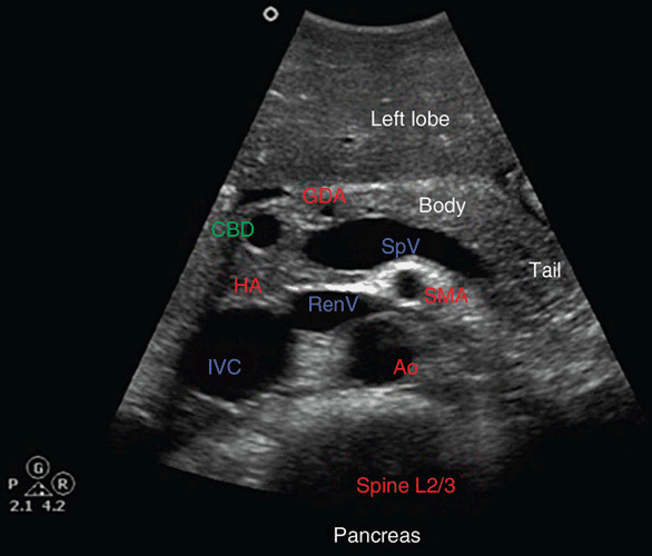
  • On ultrasound, the pancreas is located in the upper abdomen between the stomach (anteriorly) and the major vessels (posteriorly). A useful landmark is the Splenic Vein, which lies posterior to the body/tail of the pancreas. 

  • The normal sonographic appearance: usually homogeneous echotexture, often isoechoic to slightly hyperechoic compared to the liver, though increasing fatty infiltration with age may make it more echogenic. 

  • Normal duct diameter: The main pancreatic duct (MPD) is typically ≤ 2–3 mm. In the head region the common bile duct (CBD) is also visible (normal 4 mm) when well-seen. 

Technique & scanning tips

  • Patient preparation: Fasting (6+ hours) helps reduce bowel gas and improves visualization. 

  • Transducer selection: Use a curved array (e.g., 3–6 MHz) appropriate for penetration; in thinner patients higher frequency may be used. 

  • Approach:

    • Start high in the epigastrum, transverse orientation, locate aorta/IVC as deep landmarks, then identify splenic vein and the gland above it. 

    • To visualize the tail of the pancreas, a left inter-costal or subcostal approach using the spleen as acoustic window may be required. 

    • Sweep through head → neck → body → tail, in both transverse and longitudinal planes.

Measurements (normal reference)

  • Sizes vary with age, habitus. Approximate normal values: head ≈ 35mm anterior–posterior, neck ~10-15mm, tail ~20mm (though wide variability). 

  • Because pancreatic size correlates poorly with body size or age, the focus is often on morphology rather than exact measurements. 

Common pathologies & ultrasound findings

  • Acute or chronic pancreatitis: gland enlargement, heterogeneity, increased echogenicity (in chronic), calcifications, duct dilatation. 

  • Pancreatic cysts / pseudocysts: anechoic or complex fluid‐filled areas, often with history of pancreatitis.

  • Pancreatic adenocarcinoma or mass lesions: focal hypoechoic or heterogeneous masses, duct obstruction, vascular involvement. 

  • Lipomatosis/fat infiltration: increased echogenicity of the gland.

Clinical tips

  • Always scan in more than one plane; a single view may miss pathology or mischaracterize.

  • Use surrounding vascular landmarks (splenic vein, SMV, aorta) to reliably locate the pancreas.

  • Be aware of limitations: bowel gas, patient habitus can degrade image quality.

  • Document both normal and abnormal sections: size, contour, echotexture, ductal changes, calcifications.


2. Spleen

https://i.ytimg.com/vi/E8P6VLhKLEU/maxresdefault.jpg
8

Normal anatomy & appearance

  • The spleen lies in the left upper quadrant (LUQ), typically posterior, adjacent to diaphragm, stomach, and left kidney. It is intraperitoneal. 

  • On ultrasound, normal spleen: homogeneous echotexture, often slightly more echogenic than the kidney. 

  • Normal size: According to measurement studies, upper limit of length ~12-15 cm in adults (varies with body size).

Technique & scanning tips

  • Patient preparation: Fasting may help reduce interfering bowel gas.

  • Approach: Subcostal or intercostal window in the left lateral decubitus or supine with left arm raised may improve access. The spleen can be visualized between ribs.

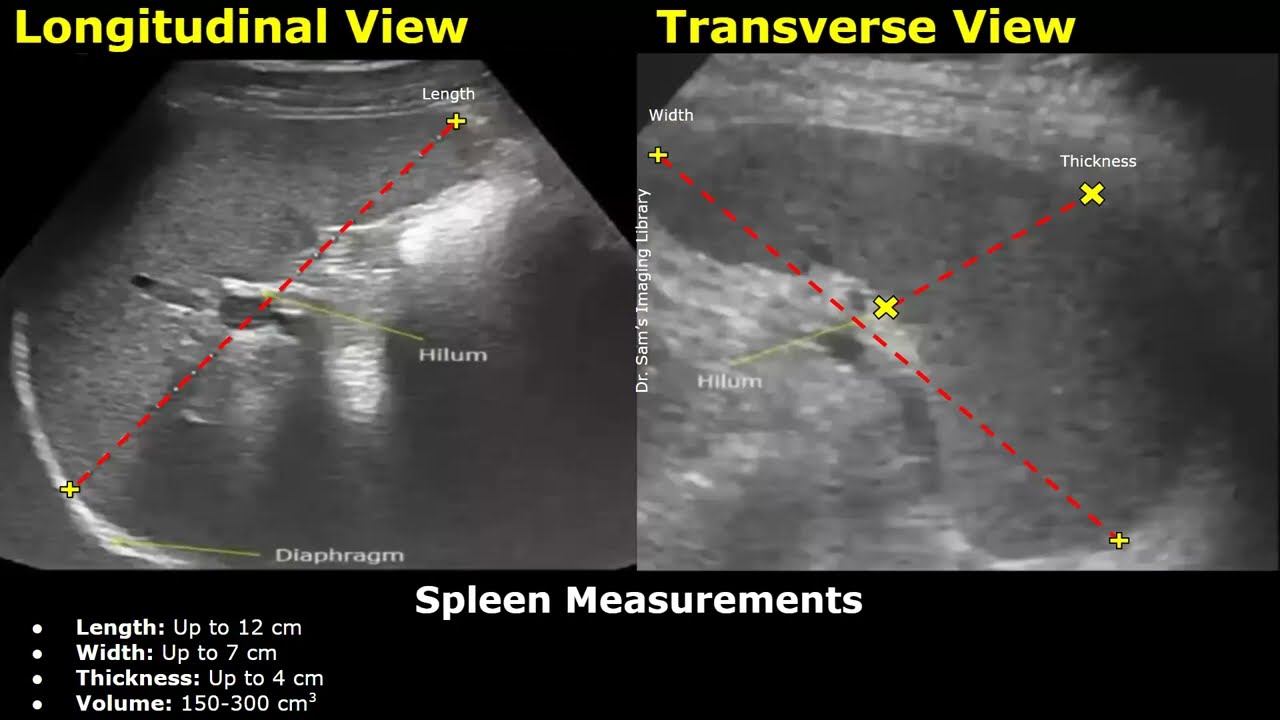
  • To measure: Place probe longitudinally (often between ribs), align with longest axis of spleen from upper pole (near diaphragm) to lower pole. Width (medial-lateral) and thickness (anterior–posterior) can be measured. 

Measurements (normal reference)

  • Length: ~11–13 cm typical in many adults; however individual variation significant. 

  • Thickness: 6 cm often used as cutoff when length borderline.

Common pathologies & ultrasound findings

  • Splenomegaly: enlarged spleen, rounded contour, may extend below left kidney. 

  • Trauma / splenic laceration: irregular parenchymal defects, subcapsular hematoma, free fluid in splenorenal recess (“Koller’s pouch”). 

  • Cysts / infarcts / abscesses: focal areas of altered echogenicity, fluid collections. 

  • Accessory spleen (splenule): small extra nodules with similar echogenicity to spleen; common (≈10%)

Clinical tips

  • When measuring spleen, use consistent anatomical landmarks and scan plane to compare serially.

  • Assess for perisplenic fluid (especially in trauma).

  • Compare echogenicity of spleen to kidney (spleen often more echogenic than left kidney) as a quick check of texture.

  • Document any focal lesions, contour changes, surrounding fluid.


Summary Comparison Table


Organ Key Landmarks Normal Appearance Major Pathology Indicators
Pancreas Splenic vein, aorta, IVC/SMV Homogeneous, isoechoic/hyperechoic gland Mass, cyst, duct dilatation, calcifications, heterogeneity
Spleen Diaphragm, left kidney, ribs Homogeneous, slightly more echogenic than kidney; length ~14 cm Enlargement, focal lesions, perisplenic fluid
Wednesday, 22 October 2025 15:10

GALLBLADDER

Written by


Normal Gallbladder Appearance

https://i.ytimg.com/vi/gkBNS5MgnuU/maxresdefault.jpg?rs=AOn4CLBnjIRumtewCAYi1GJ2V423wMZ8JA&sqp=-oaymwEmCIAKENAF8quKqQMa8AEB-AH-CYAC0AWKAgwIABABGGUgZShlMA8%3D
6

Key features:

  • Pear-shaped, anechoic lumen (fluid filled) with clearly defined wall. 

  • Wall thickness ≤ 3 mm when fully distended and in a fasted state. 

  • Normal dimensions: about 7-10 cm in length, ~3-4 cm in transverse diameter in a fasted adult. 

  • No intraluminal echogenic foci with shadowing, no wall irregularity or surrounding fluid.

Technique tips:

  • Have the patient fast (often 6-12 h) so the gallbladder is distended and easily imaged. 

  • Use the liver as an acoustic window (right upper quadrant, subcostal or intercostal) to reduce bowel gas interference. 

  • Scan both long axis and short axis, and fan through to cover fundus, body, and neck.


🚨 Abnormal Appearances & Common Pathologies

Below are key abnormal findings, what they look like on ultrasound, and what they may represent.

1. Gallstones (Cholelithiasis)

https://jetem.org/wp-content/uploads/2017/01/WES-Ultrasound-Upright-Annotated.-JETem-2017.jpg
4

USG appearance:

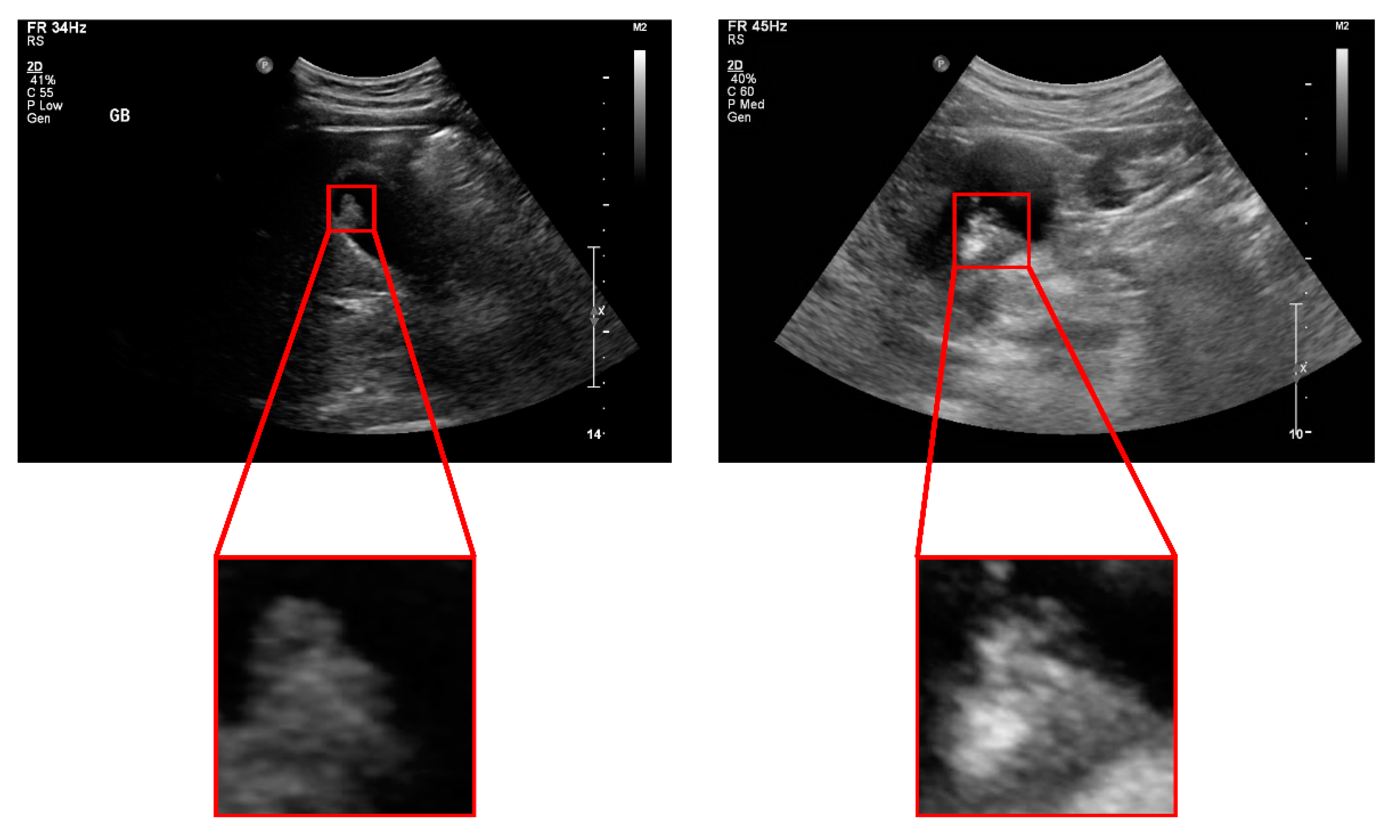
  • Hyperechoic (bright) foci within the lumen with posterior acoustic shadowing (regardless of stone composition). 

  • Mobility of stones when patient position changes (if not impacted).

  • A classic sign: the “WES sign” (Wall-Echo-Shadow) when gallbladder is packed with stones. 

Clinical note: Stones are a common finding in gallbladder ultrasound and may warrant further management depending on symptoms.


2. Gallbladder Sludge

https://www.researchgate.net/publication/7895268/figure/fig1/AS%3A484131197984768%401492437280459/Ultrasonographic-image-of-biliary-sludge-in-gallbladder-without-acoustic-shadow.png
4

USG appearance:

  • Low-level, non-shadowing echoes layering in dependent portion of lumen.

  • May change with patient position but slower than free fluid.

  • No significant posterior shadowing (distinguishing from stones).

Clinical note: Sludge may represent biliary stasis; may predispose to stones or cholecystitis.


3. Acute Cholecystitis

https://www.augusta.edu/colleges/medicine/ultrasound-education/images/gicoursepic2.png
4

USG appearance:

  • Wall thickening > 3 mm. 

  • Distended gallbladder (often > 10 cm length) with gallstones impacted in neck or cystic duct.

  • Pericholecystic (surrounding) fluid or edema. 

  • Positive sonographic Murphy’s sign: maximal pain when ultrasound probe presses over gallbladder. 

Clinical note: Combined with clinical findings (RUQ pain, fever, WBC), these features support acute cholecystitis diagnosis.


4. Chronic Cholecystitis / Gallbladder Wall Thickening

https://www.smartsonographer.com/uploads/2/7/1/7/27170197/adenomyomatosis-2_orig.gif
4

USG appearance:

  • Diffuse or focal wall thickening (may mimic inflammation). 

  • Features of Adenomyomatosis of gallbladder: Rokitansky-Aschoff sinuses (small intramural cystic spaces) and “comet tail” artefact. 

Clinical note: Wall thickening may have multiple causes (inflammation, edema from systemic disease, neoplastic), so context is key.


5. Gallbladder Cancer / Mass-forming Lesions

https://www.mdpi.com/jcm/jcm-10-03585/article_deploy/html/images/jcm-10-03585-g001.png
4

USG appearance:

  • Focal intraluminal mass or thickened wall, often heterogeneous echotexture. 

  • Irregular margins, possible calcifications, and may show invasion into liver parenchyma or adjacent structures.

  • Large gallbladder polyps (>10 mm) may raise suspicion for malignancy. 

Clinical note: Suspicious features on ultrasound warrant further imaging (CT/MRI) and surgical consultation.


📝 Summary Table: Normal vs Abnormal Features


Feature Normal Abnormal (Pathology)
Gallbladder shape & lumen Pear-shaped, anechoic lumen Distended with stones/sludge or collapsed/contracted
Wall thickness ≤ 3 mm > 3 mm (in inflammation) or significantly thick/mass-forming
Intraluminal echoes None (just bile) Hyperechoic stones with shadow, low-level sludge echoes
Mobility of intraluminal content Free flow Impacted stones, polyps fixed to wall
Surrounding fluid/edema None Pericholecystic fluid (in cholecystitis)
Mass or polyp presence Absent Intramural mass, large polyp, wall irregularity
Wednesday, 22 October 2025 14:11

LIVER ULTRASOUND

Written by


Liver Ultrasound Probe Positioning and Transducer Placement for Liver Scanning (Abdominal USG)

1. Left Lobe of Liver (Transverse View)


• Place the probe in the midline under the costal margin in transverse orientation.

• Ask the patient to take a deep breath to bring the liver into view.

• Structures visualized: Left lobe, caudate lobe, and left portal vein (LPV).

2. Left Lobe of Liver (Longitudinal View)


• Rotate the probe 90° clockwise into longitudinal orientation.

• Sweep towards the left upper quadrant to visualize the splenic vein, splenic artery, and stomach.

• Identify the pancreas and edge of the left lobe.

3. Porta Hepatis and Bile Duct


• Keep the probe in longitudinal orientation and move slightly to the right.

• Identify the portal vein and its entry into the liver (porta hepatis).

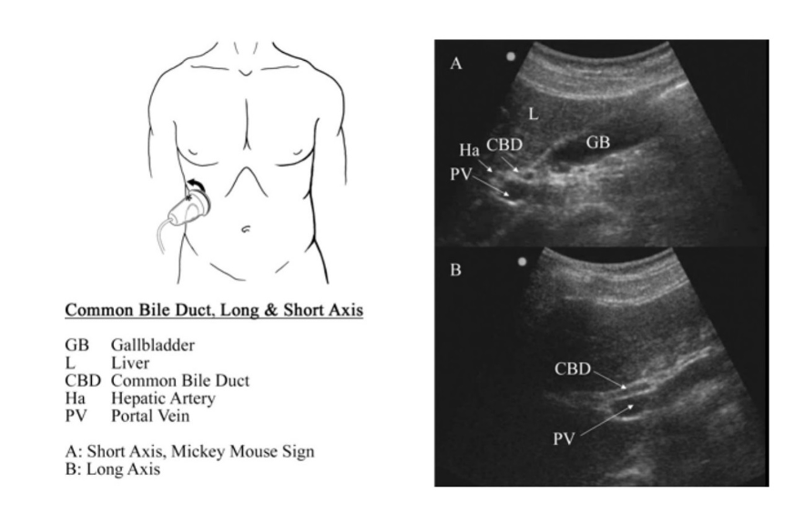
• Rotate slightly anticlockwise to locate the common bile duct (CBD).

4. Right Lobe and Hepatic Veins (Transverse View)


• Place the transducer parallel and just below the right costal margin in transverse orientation.

• Ask the patient to take a deep breath to visualize hepatic veins and IVC.

• Structures visualized: Right hepatic vein (RHV), middle hepatic vein (MHV), and left hepatic vein (LHV).

5. Right Lobe Medial to Kidney (Longitudinal View)


• Move the probe further to the right of the patient.

• Sweep left and right to visualize the right lobe and its relation to the kidney.

• Structures visualized: Hepatic veins, portal veins, gallbladder.

6. Right Lobe and Hepatic Veins (Oblique Subcostal View)


• During deep inspiration, angle the probe toward the patient’s right shoulder.

• Scan under the costal margin to evaluate hepatic veins and their drainage into the IVC.

Key measurements & normal reference values

https://i.ytimg.com/vi/A3akbgBKmcw/maxresdefault.jpg?rs=AOn4CLDRG9GNyMbhLk7QZTePYMr36IndDQ&sqp=-oaymwEmCIAKENAF8quKqQMa8AEB-AH-CYAC0AWKAgwIABABGGsgayhrMA8%3D
6

1. Craniocaudal (CC) length

  • The CC length is measured in a sagittal or oblique longitudinal plane, typically in the right lobe of the liver, often along the right mid-clavicular line (MCL). 

  • One strongly referenced method: from the uppermost right hemi-diaphragm to the inferior tip of the right lobe, through a horizontal line parallel to the anterior liver wall. 

  • Normal adult values: In the MCL measurement, values >15.5-16 cm are often considered enlarged. 

  • Example: A study found for the adult right lobe: 13.0 ± 1.5 cm for females and 14.1 ± 1.3 cm for males. 

  • Technique tip: Patient supine, take a deep inspiration (which lowers diaphragm and pulls liver down) to better visualize the dome and inferior border. Use longitudinal plane, good acoustic window. 

2. Transverse diameter (Width)

  • The transverse diameter is measured in a transverse/axial plane, typically the widest span of the liver from side to side. 

  • Typical normal range: ~20-23 cm in adults. 

  • Technique tip: Place the probe in a transverse orientation (often subcostal or intercostal) sweeping across to capture maximum lateral extent of liver.

3. Anteroposterior (AP) (Depth) measurement

  • AP measurement captures the depth/“thickness” of the liver in the anterior-posterior dimension. 

  • Some studies report the AP dimension for liver in healthy adult volunteers: ~15.8 ± 1.9 cm (CI 12.6/19.8 cm) in one MRI-based study (useful benchmark though not USG). 

  • In ultrasound practice, AP measurements are used less often than CC/width for routine hepatomegaly screening, but can be useful adjuncts.

4. Volume estimation

  • Liver volume can be estimated using formulae derived from linear measurements. For example, in the referenced video description:

    Liver Volume (cm³) = 343.71 + [0.84 × A × B × C]
    Where:

    • A = Left lobe AP diameter

    • B = Craniocaudal length

    • C = AP measurement (Right lobe) 

  • Important caveat: Correlation between simple linear dimensions and true volume isn’t perfect; one study found poor correlation (CC r = 0.393, AP r = 0.359) using MRI as reference. 

  • Technique tip: Ensure consistent measurement planes, avoid oblique angulation, and use same protocol if doing serial follow-up.


Step-by-step measurement approach

https://www.researchgate.net/publication/328119743/figure/fig4/AS%3A678713821761538%401538829393532/A-Ultrasound-cross-section-of-the-liver-trough-subcostal-access-SP-width-of-the-liver.jpg
6
  1. Patient position & preparation

    • Supine position, consider slight head-end elevation.

    • Ask deep breath hold to lower the diaphragm. 

    • Use subcostal and intercostal windows as needed (especially if rib shadowing/gas). 

  2. Locate appropriate lobe and plane

    • For CC length: Move probe to right mid-clavicular line (or mid-axillary line in some studies) in longitudinal orientation. Visualise from hepatic dome (under diaphragm) to inferior tip of right lobe. 

    • For transverse diameter: Place probe transversely across liver, sweep to capture maximum lateral span.

    • For AP depth: Use image where liver appears in transverse/axial or oblique section and measure front-to-back (anterior to posterior).

  3. Place measurement calipers correctly

    • Ensure measurement is along a straight line (not curved), parallel to anterior liver wall for CC. 

    • Avoid rib shadows, bowel gas. Use acoustic windows carefully.

    • Document respiratory phase — ideally during breath hold.

  4. Record values & compare to reference ranges

    • For example: CC length >15.5-16 cm may suggest hepatomegaly. 

    • Transverse ~20-23 cm typical normal in adult.

    • Keep consistent protocol if doing serial measurements.

  5. Volume estimate (if required)

    • Use formula if validated in your institution. Be cautious of limitations: linear measurement approximations may not reflect actual volume accurately. 

    • Document method used for volume calculation (e.g., “Liver volume estimated via [method]”).


Pitfalls & practical tips


  • The full inferior tip of the right lobe may be difficult to visualise (rib shadowing, patient habitus) — thus measurement may be underestimated. 

  • Body habitus (obesity, large waist circumference) can influence liver size and measurement accuracy. 

  • Different operators/machines might get slightly different values — hence intra- and inter-observer consistency matters. 

  • Ensure measurement plane is reproducible for follow-up studies.

  • Be aware of anatomical variants like a Riedel’s lobe (which may increase apparent size without pathology). 


Overview

Health Africa is a tight-knit community of scientific, medical, and life sciences experts that produce and share the latest information, in a readable, understandable way. Also join our social nework group  Health Africa Conference for convenient communication. 

Get Support

For All Enquiries Contact Us

  • Mombasa, Kenya
  • +254 713 521 930
  • info@healthafricalibrary.co.ke

Login Form

Register to save more

Register an account today and get great deals, offers and customised products only for you.

  • Secure registration form
  • Your data on your hand, you can update anytime
  • Save your favourite products and access anytime
  • Order products easily.